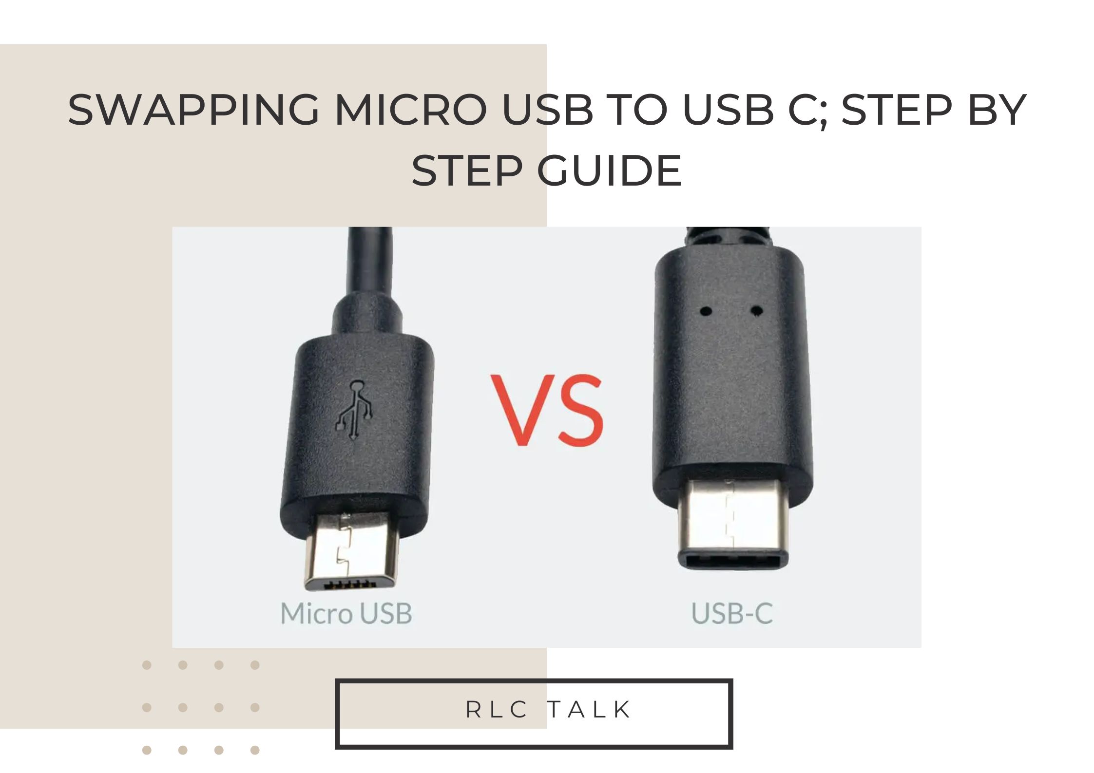
Swapping Micro USB to USB C; Step By Step Guide
Can you change the USB port to Type-C? The use of 8-pin or 10-pin USB-C connectors with only power pins is the straightforward fix in this situation. All of the GND pins and all of the VBUS pins can be simply shorted together or connected together and used for USB.
In this article, you will find everything you need to know when trying to swap a micro USB to a USB C. So stick around until the end to find out what you’ve been looking for.
Key technical differences between USB Type-C and micro USB
Here are some key technical differences between USB Type-C and micro USB:
Connector Type: The USB Type-C connector is a 24-pin reversible connector, while the micro USB connector is a 5-pin connector that is not reversible.
Power Delivery: USB Type-C supports Power Delivery (PD) protocol, which enables the device to draw more power for faster charging. In contrast, microUSB only supports charging up to 5V/2A.
Data Transfer Speed: USB Type-C supports USB 3.1, which has a data transfer speed of up to 10Gbps, while micro USB 2.0 has a maximum data transfer rate of 480Mbps.
Charging Speed: USB Type-C supports fast charging up to 100W, while micro USB only supports up to 15W.
Audio and Video: USB Type-C supports DisplayPort, HDMI, and VGA protocols, which allows it to transmit both audio and video signals. MicroUSB does not support these protocols, so it cannot transmit audio or video signals.
Compatibility: USB Type-C is compatible with a variety of devices and protocols, including Thunderbolt 3, while micro USB is only compatible with USB 2.0 and USB 3.0 protocols.
Overall, USB Type-C offers more versatility, faster data transfer and charging speeds, and support for more advanced protocols compared to micro USB.
The Rainbow of Solder Mask Colors: Which is Right for Your PCB?
rlc talk
Swapping micro USB to USB C in PCB; How can it be done easily?
Swapping a micro USB connector to a USB-C connector on a PCB (printed circuit board) can be a bit tricky, but it is possible with the right tools and techniques. Here are the steps you can follow:
Step 01: Identify the pinout of the micro USB connector on the PCB.
You can do this by referring to the schematic or the PCB layout of the device. Note down the pinout of each pin, including the power and ground pins.
Step 02: Remove the micro USB connector from the PCB.
You can use a soldering iron and desoldering wick to remove the connector. Be careful not to damage any other components on the board.
Step 03: Clean the solder pads on the PCB where the micro USB connector was removed.
Use a soldering iron and solder wick to remove any remaining solder and flux residue.
Step 03: Prepare the USB-C connector.
Make sure you have the right USB-C connector for your application. Check the pinout of the connector and ensure it matches the pinout of the micro USB connector.
Step 04: Solder the USB-C connector to the PCB.
Place the USB-C connector on the PCB and align the pins with the solder pads. Apply solder to each pin, making sure the connection is strong and clean. Use a multimeter to test the connection between the USB-C connector and the PCB.
Step 05: Test the connection.
Once the USB-C connector is soldered in place, test the connection to ensure it is working properly. Connect a USB-C cable to the connector and test the device.
Step 06: Finalize the design.
If the connection is working properly, finalize the design of the PCB by making any necessary changes to the schematic or layout.
Note that this process requires some knowledge of PCB design and soldering. If you are not familiar with these techniques, it may be best to seek the help of a professional electronics engineer or technician.
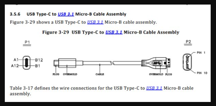
Micro USB to USB-C wiring diagram
How to swap USB-C to USB-A?
Step 01: Obtain the required components
You will need a USB Type-C connector, a USB-A connector, and a cable with wires that are compatible with both connectors. It’s important to choose a cable that has sufficient gauge (thickness) to carry the current that you need.
Step 02: Strip the ends of the cable
Using a wire stripper or a razor blade, carefully strip the insulation off the ends of the cable to expose the wires inside. You should have four wires: red (power), black (ground), green (data-), and white (data+).
Step 03: Prepare the USB connectors
Using a small screwdriver or pliers, open the metal housing of the USB Type-C and USB-A connectors. This will expose the pins that you need to solder to.
Step 04: Solder the wires
Tin the ends of the wires by heating them with a soldering iron and applying a small amount of solder. Then, insert the wires into the appropriate pins on the USB connectors, and solder them in place. The pinout for USB Type-C is different from that of USB-A, so make sure you use the correct pinout for each connector.
Step 05: Insulate the connections
After soldering the wires, use heat shrink tubing or electrical tape to insulate the connections and prevent them from touching each other. Make sure that the insulation covers the entire exposed area of the wires, and that it is securely fastened in place.
Step 06: Test the cable
Once you have finished making the cable, test it by connecting it to your devices and checking if it works as expected. You can use a multimeter to check the continuity of the wires and make sure there are no short circuits.
Creating a DIY USB Type-C to USB-A cable can be challenging, and it’s important to exercise caution when working with electrical components. If you are not experienced with soldering or wiring, it may be best to seek help from someone who is more experienced or purchase a pre-made cable.
Why Type-C is better than micro USB?
There are several reasons why Type-C is considered better than micro USB. Here are some of the key points:
- Reversibility
One of the most significant advantages of Type-C over micro USB is its reversible design.
With a Type-C connector, you can plug the cable into your device in any orientation, which means you no longer have to worry about whether you’re inserting it the right way up or not. This is a significant convenience factor that saves you time and frustration.
- Faster Data Transfer and Charging Speeds
Type-C supports USB 3.1, which provides faster data transfer speeds compared to micro USB.
USB 3.1 is capable of transferring data at speeds of up to 10 Gbps, which is two times faster than USB 3.0 and up to 20 times faster than USB 2.0. Additionally, Type-C supports faster charging speeds, with some devices capable of charging at up to 100W.
- Compatibility
Type-C is more versatile than micro USB because it can support a wide range of protocols and standards, including USB 3.1, Thunderbolt 3, DisplayPort, HDMI, and VGA.
This means you can use a single Type-C cable for a variety of purposes, such as charging, data transfer, and video output.
- Durability
Type-C connectors are more durable than micro USB connectors. Type-C connectors are designed to withstand more insertions and removals compared to micro USB connectors, which means they are less likely to break or become loose over time.
- Future-proofing
Type-C is the future of USB connectivity. With more and more devices adopting Type-C, it’s becoming the new standard for USB connectivity.
By investing in Type-C devices and accessories, you’re future-proofing yourself against the need to upgrade your cables and accessories every time a new standard is introduced.
In summary, Type-C is better than micro USB because it’s more convenient, faster, more versatile, more durable, and future-proof.
How Much Does It Cost To Make A PCB – Latest Update In 2023
rlc talk